In industrial heat transfer systems, whether in the petrochemical industry, food industry, large-scale district cooling and heating in HVAC systems, or precise temperature control and prevention of cross-contamination in the pharmaceutical industry, plate heat exchangers have become essential equipment in modern thermal engineering due to their significant advantages such as high-efficiency heat transfer, compact structure, flexible combination, and ease of maintenance.
In practical industrial applications, maximum pressure is often one of the core parameters determining whether equipment can operate safely and stably for a long time. This parameter not only directly affects the selection criteria and structural design of the equipment, but is also closely related to production safety, system reliability, and total life cycle cost. Once the operating pressure exceeds the equipment's design limit, it can lead to sealing failure and media leakage, resulting in energy waste and environmental pollution; in severe cases, it may cause serious safety accidents such as plate deformation, gasket extrusion, or even equipment explosion.
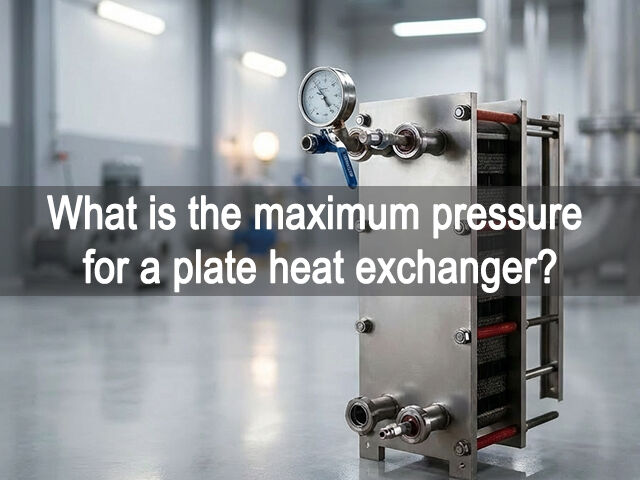
The maximum pressure of a plate heat exchanger generally refers to the highest permissible operating pressure that the equipment can withstand continuously at a specific temperature without leakage or structural damage.
It's one of the first questions engineers ask during selection: "What's the maximum pressure this unit can take?" The honest answer is — there's no single number. Pressure limits depend on plate material, gasket design, corrugation geometry, and the clamping system working together.
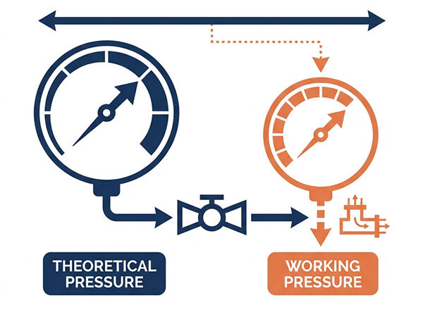
In technical parameters, we often see two concepts:
1.1 Design Pressure
The theoretical maximum pressure set by the manufacturer according to standards (such as NB/T 47004, ASME, PED, etc.).
1.2 Operating Pressure
The operating pressure of the equipment in actual operation. It should generally be lower than the design pressure, with a safety margin.
For plate heat exchangers, this pressure value is not a single number; it varies with multiple factors, including the medium, temperature, plate material, and sealing system.
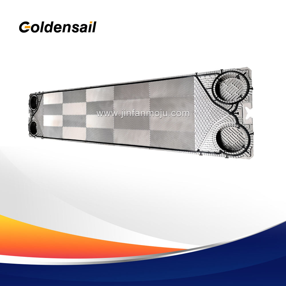
Unlike shell-and-tube heat exchangers, the pressure-bearing capacity of a plate heat exchanger does not depend on the thick shell, but on the combined strength of the thin plates and gaskets.
2.1 Plate Material
The usual candidates are 304 and 316L stainless steel, titanium, and Hastelloy — each with a different yield strength that sets the threshold between elastic recovery and permanent PHE Plate deformation under pressure. Pick the wrong material for the pressure class and no amount of structural reinforcement will save the plate geometry long-term.
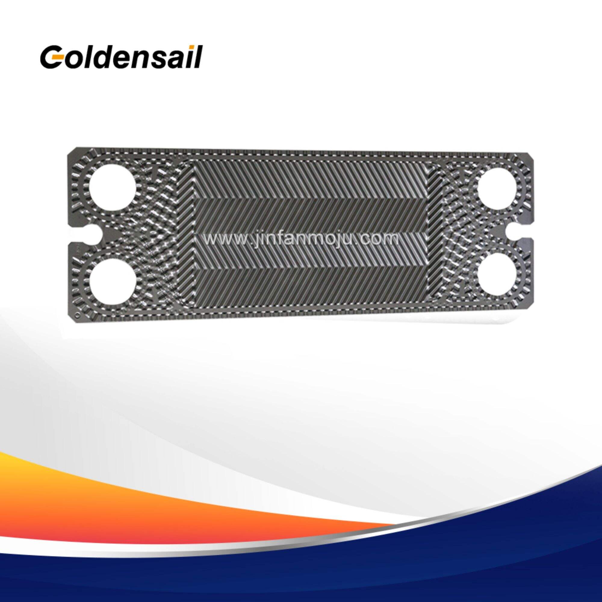
2.2 Plate Thickness
Most standard Heat Exchanger Plates fall in the 0.5–0.8mm range, which covers the majority of general-duty applications. Where operating pressure pushes beyond that envelope, JINFAN's thicker PHE Plate options — 1.0mm and above — bring a higher section modulus into play, and that's what actually moves the pressure-bearing needle.
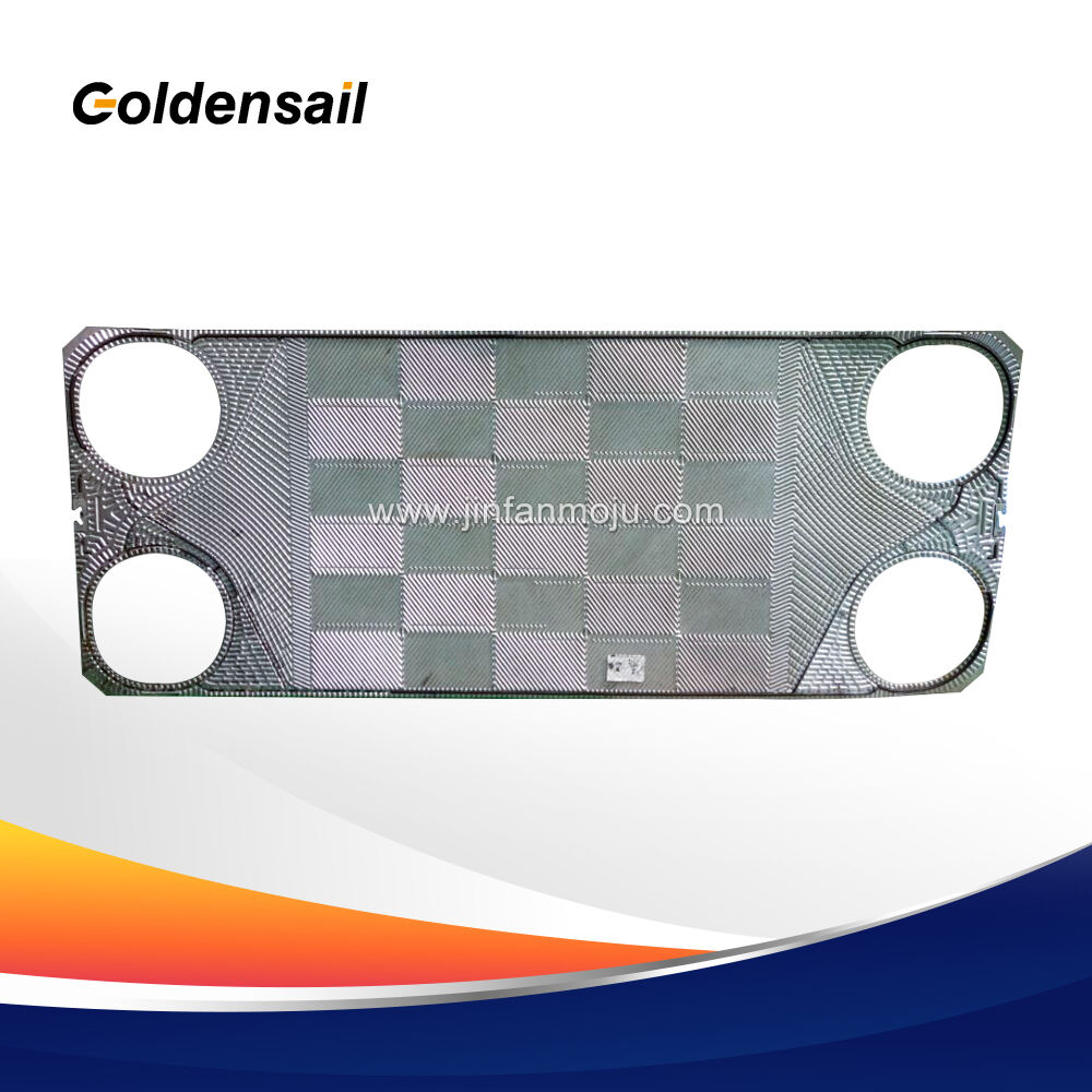
2.3 Gasket Material and Cross-Section
Under high-pressure conditions, gaskets are prone to "extrusion," leading to leakage. JINFAN's high-performance gaskets and special designs effectively improve the sealing pressure resistance level. Typically, the maximum working pressure of conventional plate heat exchangers is between 1.0MPa and 1.6MPa, while high-pressure designed models can reach 2.5MPa or even higher.
2.4 Corrugation Depth and Plate Type
Shallow-corrugated plates pack: in more contact points across the plate surface, giving the structure solid mechanical backing and a higher tolerance for pressure, though you'll pay for it with a steeper pressure drop.
Deep-corrugated plates: work the opposite way, the wider channels handle bigger flow volumes well, but with fewer points of plate-to-plate contact, they don't take kindly to pressure spikes and are better kept in low-pressure, high-throughput service.
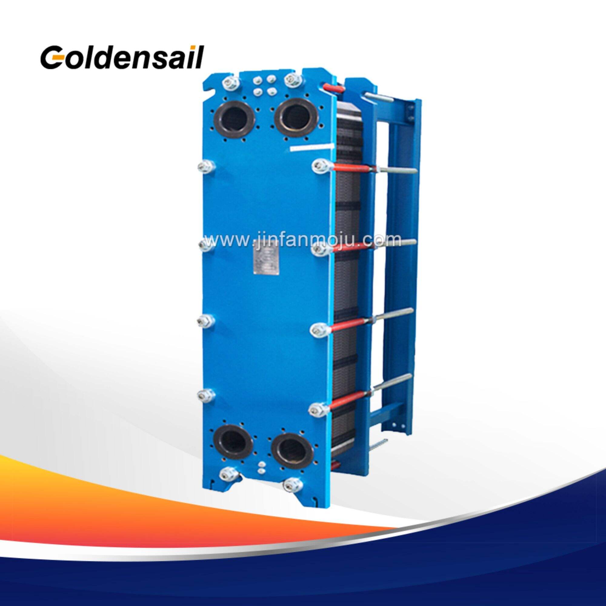
2.5 Clamping Bolts and Frame Plates
The frame and tie rods have to generate enough clamping force to counteract internal pressure across the entire plate pack. In high-pressure applications, this means heavier frame plates, larger-diameter bolts, and reinforced support legs. Pressure surges can bow the frame or snap the tie rods.
Different regions globally have different specifications for the pressure design of plate heat exchangers:
European Standard (PED 2014/68/EU): Strict classification of pressure equipment. If the medium is a hazardous fluid or the pressure-volume product is large, the equipment must be CE certified.
American Standard (ASME): Typically requires plate heat exchangers to have a "U" stamped certification, suitable for high-pressure, harsh conditions in the US and North American markets.
Safety Tip: One more thing worth flagging: test pressure is not operating pressure. Hydrostatic testing is a one-time strength verification — running a system continuously at test pressure will shorten equipment life or cause failure.
If you are facing high-pressure operating conditions (e.g., exceeding 1.6 MPa or involving hazardous media), it is recommended to follow these steps:
4.1 Define Parameters
Lock down your parameters first. Operating pressure, temperature, fluid corrosivity, and whether the system is subject to water hammer or pressure fluctuations — all of these shape the right design. Vague inputs lead to undersized equipment.
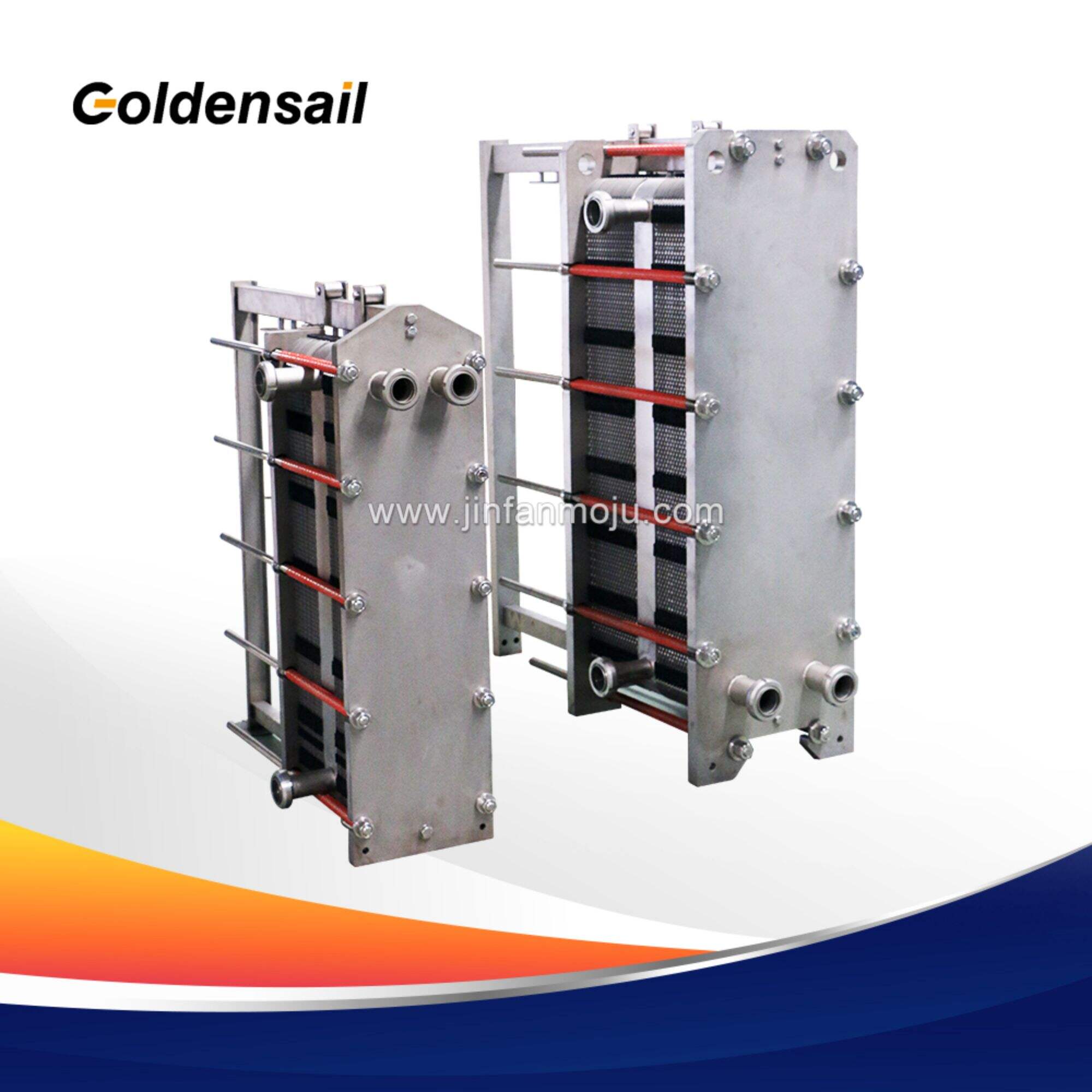
4.2 Select a High-Pressure Design
For high-pressure service, Semi-welded PHE or Fully Welded PHE should be the starting point, not an afterthought. In ammonia refrigeration and high-pressure chemical applications, the semi-welded approach bonds two plates into a single unit, which removes the gasket from the process side entirely and keeps only an external seal in place. That structural change is what pushes the working pressure ceiling to 3.0–4.0MPa. If the application demands a gasketed removable unit instead, pin down whether the supplier actually offers reinforced plates and a high-pressure gasket system rated for your conditions — not all do.
4.3 Consider Safety Accessories
A safety valve or pressure relief device on the heat exchanger inlet isn't optional in high-pressure service. Misoperation happens, thermal expansion is predictable, and without a dedicated relief path, either one can drive the system past its pressure limit before anyone catches it.
4.4 Pay Attention to Pressure Drop
Under high-pressure conditions, flow velocities are often high. It is necessary to calculate whether the pressure drop inside the heat exchanger is within the system's allowable range to avoid upstream pressure buildup or downstream underpressure due to excessive pressure drop.
Alongside these selection steps, JINFAN online plate heat exchanger sizing tool can cut down both the time and the margin for error. Manual calculations have always carried a real risk — tweak one operating parameter and the whole exercise needs to be redone, often with inconsistencies creeping in along the way. A decent online platform sidesteps that problem by running thermal calculations against verified material databases from major manufacturers in the background. You put in what you know — fluid type, inlet and outlet temperatures, allowable pressure drop, design pressure — and the tool works through the matching logic to return suitable plate types, sizes, and configurations without you having to chase down spec sheets or second-guess interpolated values.
The maximum pressure of a plate heat exchanger is not an isolated number, but a comprehensive reflection of equipment design, materials science, sealing technology, and manufacturing processes. For water-to-water heat exchange or low-pressure steam, a standard gasketed unit rated at 1.0 or 1.6MPa does the job. Once you move into high-pressure chemical processes, elevated-temperature oils, or hazardous fluids, pressure becomes a design-critical variable — not a checkbox. That's when thicker plates, semi-welded construction, and full pressure vessel certification earn their place in the specification.
 EN
EN
 AR
AR
 FR
FR
 DE
DE
 PT
PT
 RU
RU